

Hi there. This is a followup of the Programmable Paper Lantern project which I previously blogged about. Since the last time, I’ve found a much better cage design, ordered a first set of LEDs and a transformer for testing (with a more than DIY solution to power it, as you’ll see…) and I’ve, especially, made the design of the electronics that will be used in the final version. The last bit obviously happened with tremendous help from Martin, who went as far as offering me my first Arduino. And who also re-taught me the basics of electronics. Shame on me, the engineering graduate, but I must say I started almost from scratch on that, and I still know nothing but elementary survival notions.
The New Cage Design
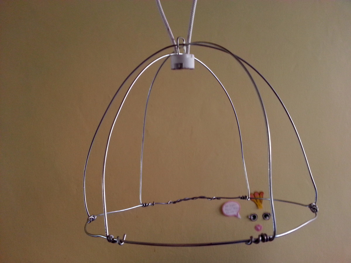
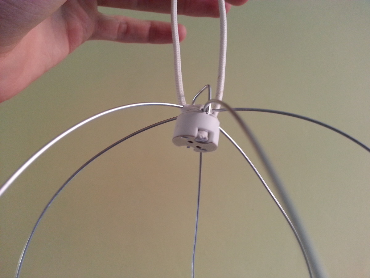
First of all, I’ve got my hands on sweet and neat needle-nose pliers. It’s quite handy to twist metallic wire around! Now my junctions are much cleaner and involve much less bending of wire, so I end up with a rounder cage. I’ve decided to drop entirely the round top of my previous design, which had been a hassle to setup, especially since I knew that my lamp holders would be much smaller than I’d first expected (my LEDs are MR16). I’ve made a straightforward round cage shape, with three wires forming the top part and intersecting in the middle. Then, I’ve just put the lamp holder across and added a bit of wire to close it.
The lamp holder has two holes, designed most likely for it to be suspended in some way (but not screwed: the ceramic used is quite fragile).What I’ve done to make sure the closing bit of wire doesn’t stick out is I made it slightly larger than the diameter of the holder. This way, the bit of wire gently presses against the outside of the holder, and the whole thing holds very easily. I’ve also added a generous amount of blu-tack to reduce the amount of play of the holder (more than you see in the last photo). This is to make sure that the LED won’t move around too much and accidentally get in contact with the paper.
It’s now time to look into what LEDs to buy and how to power them…
Different Types of LEDs
Surprisingly, there are a handful of parameters to take into account when buying LED bulbs, which can make them quite expensive. By order of importance, I considered the following:
- Wattage and power efficiency (aka. likelihood to burn the paper and then your house)
- Angle of lighting (which must be high enough to light the sides of the lantern)
- Colour temperature (wanteda warm yellows and bright whites)
- Luminosity (150 to 250 lumens being a bed lamp’s luminosity)
- Price (obviously… some LEDs are worth more than £30)
- Dimmability? My LEDs are non dimmable, I yet have to see their reaction to MOSFET+PWM dimming
I’ve bought 5W LEDs with a MR16 plug, one of them being at 3000k (warm), and the other at 4000k (white). They have a slightly above average angle of 30ish degrees. I bought these mostly because they were cheap… which enabled me to test the idea of using LEDs. To be honest, decent-range LEDs with good overall characteristics were far above my budget, in the range of £30 to even £40. Consider that I want not one but most likely a half-dozen lanterns, and you can see why it runs out of proportions.
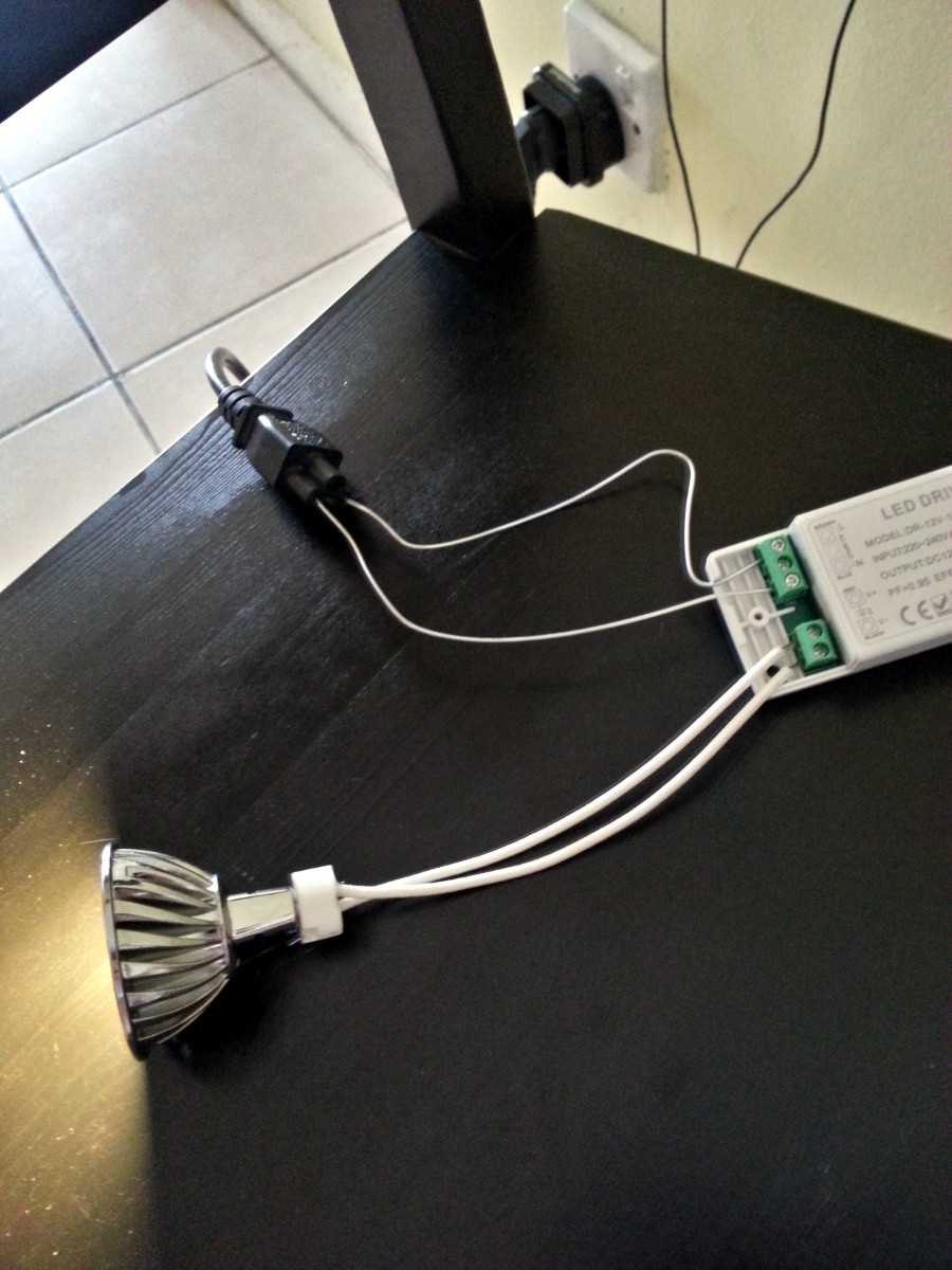
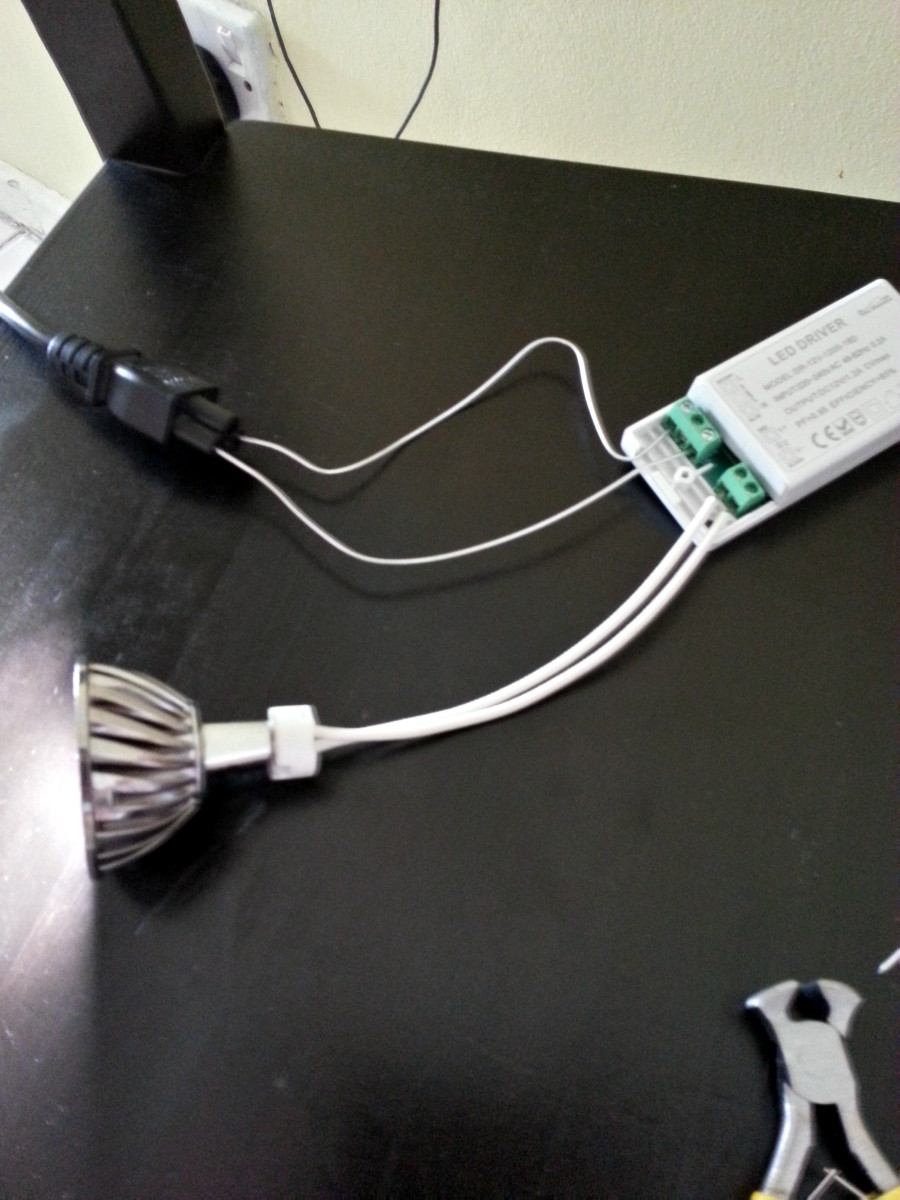
The next step to consider, once you’ve chosen the LEDs, is the transformer that will power them. I know nothing of transformers and how to choose a good one, and so Martin did it for me. My understanding is that the Volt output must be identical to the input of your LEDs and Arduino (12V and up to 12V in my case), and your Watt output only slightly superior to the combined Watt input of all your LEDs and Arduino (for me, a fair 14.4W). If your Watt output is too low, you won’t be able to light your LEDs. On the contrary, if it’s too high, you’re possibly on your way to obtaining grilled electronics.
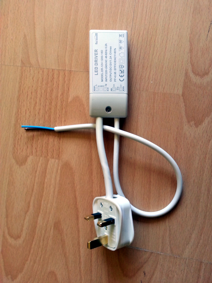
There are other things to keep in mind, such as the lowest amount of Watts that should be consumed in the circuit (which is apparently a specification of the transformer). I want to dimm my LEDs so at times I might consume close to 2-3W when all the LEDs are almost off. If that happens, I need to make sure the transformer doesn’t heat up. Make sure to validate your choices with a knowledgeable electronician, explaining her exactly what you’re going to do with the hardware. Finally, if you don’t want your prototypes to look as silly as mines, you might wanna buy cables to connect your transformer to a plug. The setup on my first photos isn’t exactly safe… But on the third picture you can see what a proper setup would look like. And obviously, if you can buy a pre-cabled transformer, go for it! It’s very hard to find cables in small quantities.
Interlude - Ça brille dans le noir
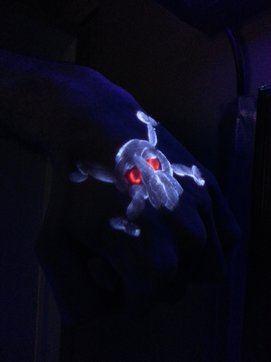
There are cool things happening at UCL and one of them is the Institute of Making Open Days. This month’s even was devoted to luminescence. I won’t make a list of all the small events that were scheduled, but I somewhat ended up with people painting on me (a recurrent hobby of my surroundings, it seems).
The paint used was UV face paint, and it looked like a mere white cream when under normal light. However, if exposed to UV lights, it glew fairly well. I’ll let you judge from the picture. I reckon it was unsettling not to have an idea what was being drawn until you saw it.
Arduino Electronics Design
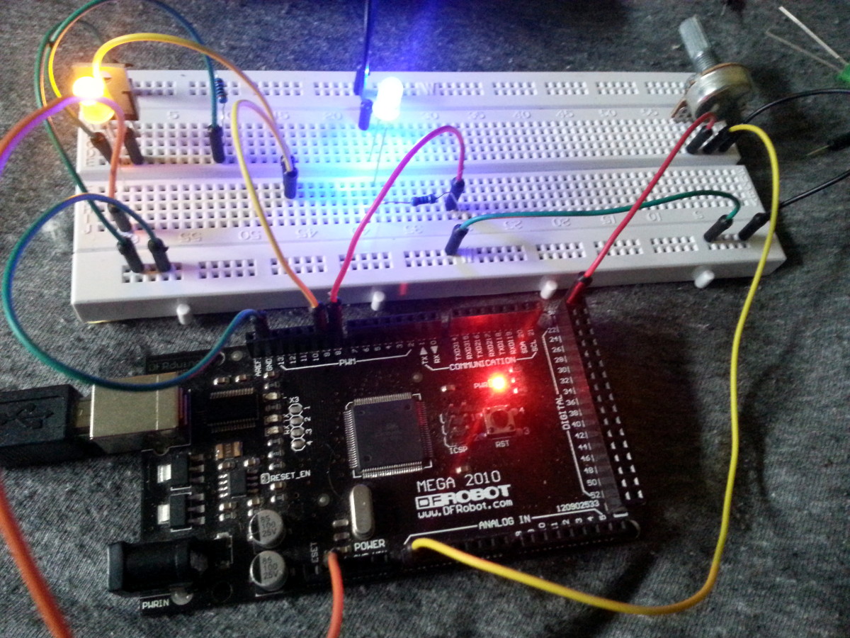
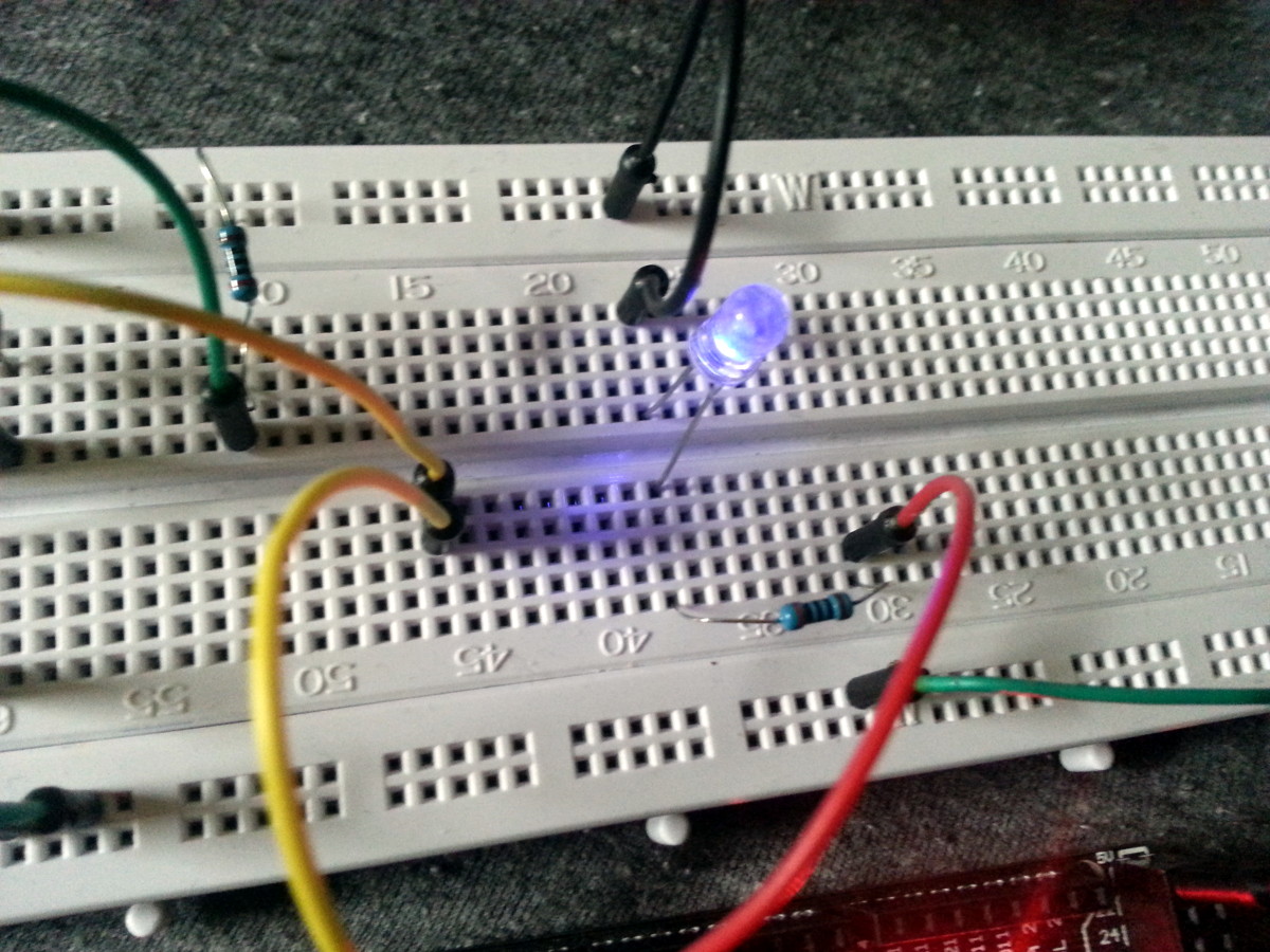
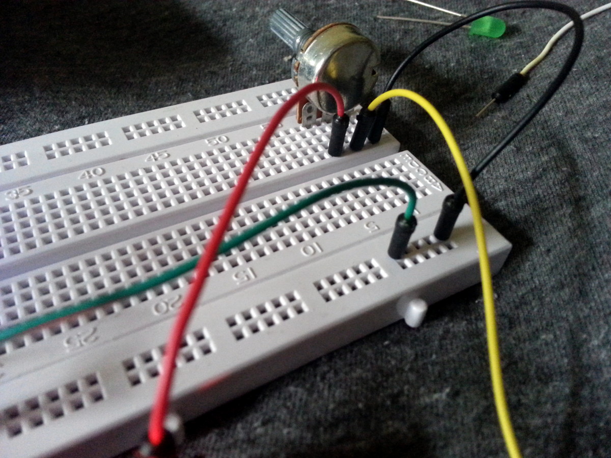
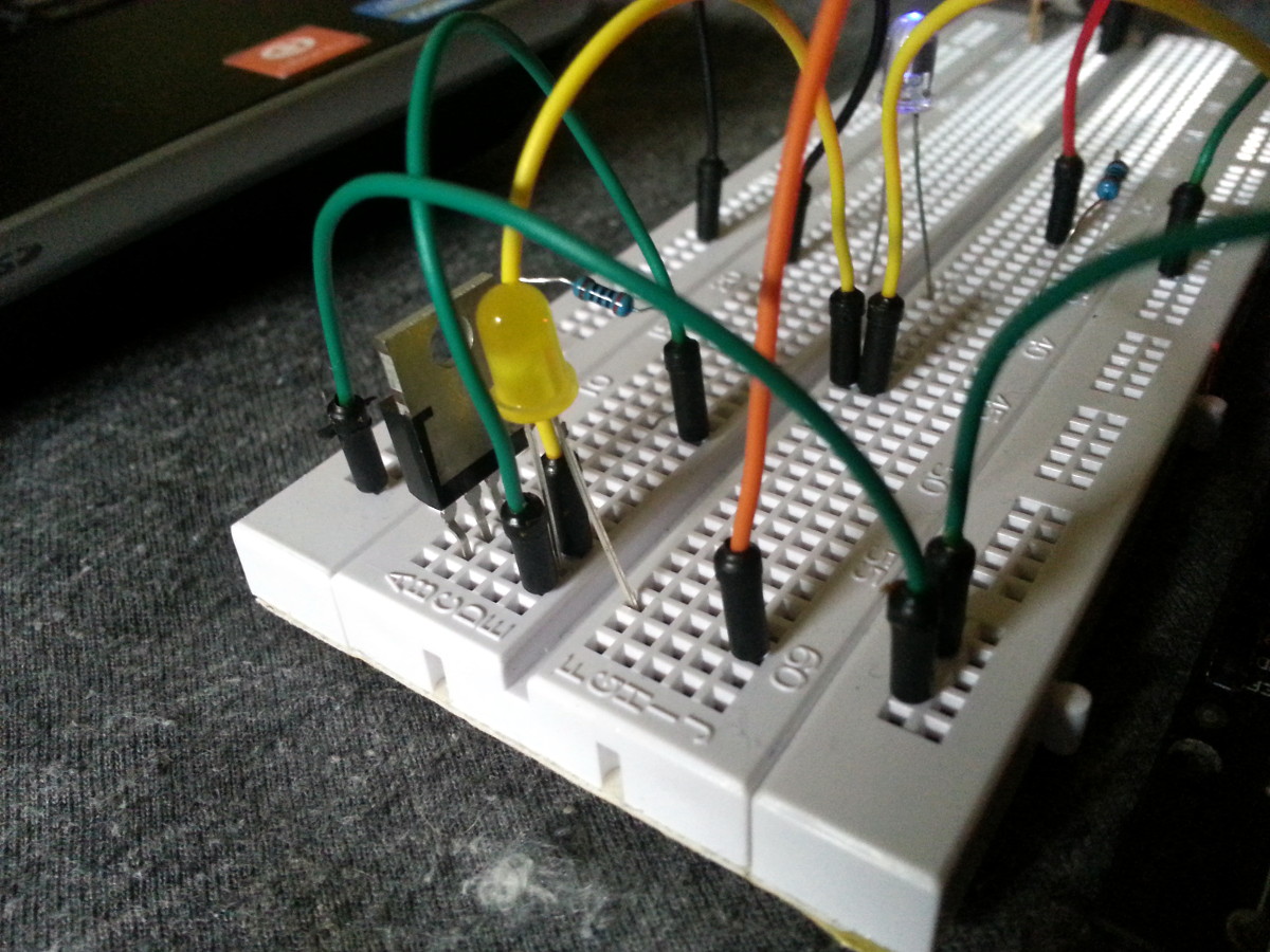
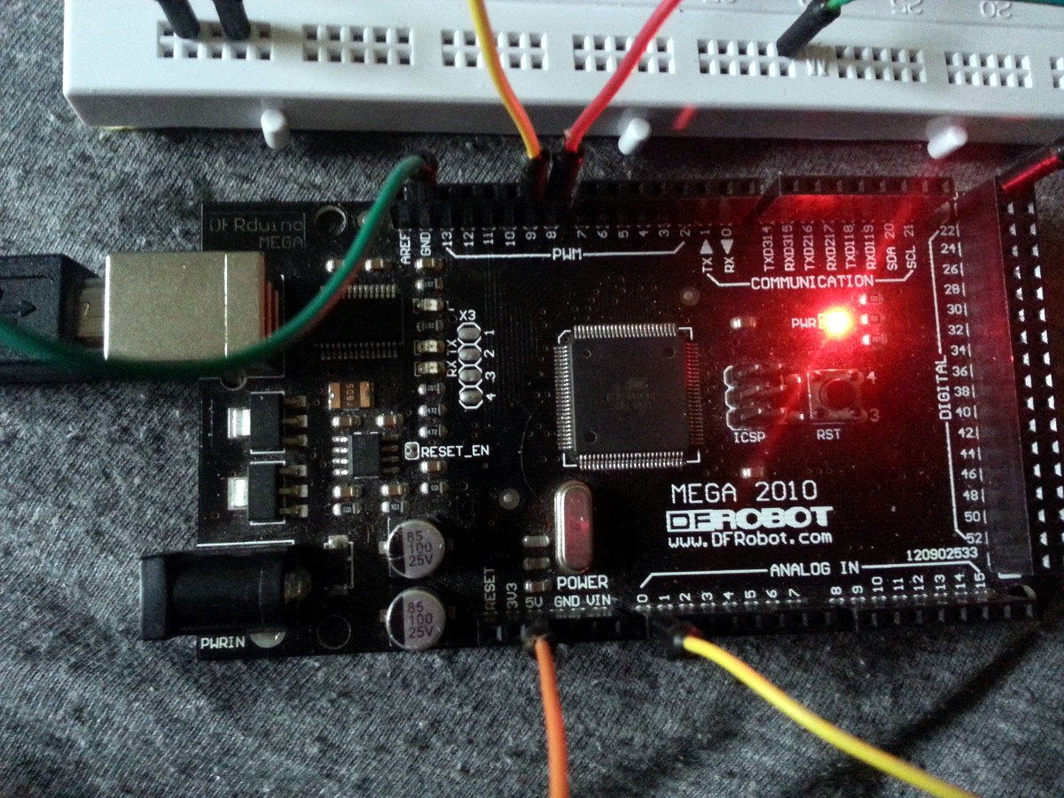
Now onto the part of the project that involves bipping and blinking. I wanted to control the brightness of the LEDs from the board, and I used here a potentiometer whose output is redirected to LEDs’ power input. The blue LED was directly powered from a PWM pin of the Arduino Mega board I used. The PWM pin takes a value between 0 and 254. If the value is, say, 64, which is roughly a fourth of 254, then the PWM output will send pulses of 5V current for a period, and then nothing for three times this period. This happens at a high frequency, and is equivalent to receiving current a forth of the original power, for the LED. As a result, the LED will shine, more or less, a forth of its maximum intensity.
For the yellow LED, I wanted to experiment the use of a MOSFET in between the LED and power source. Indeed, in the final design LEDs will not draw their power from the 5V output of the Arduino board, but rather from an external 12V source. The MOSFET will then be used to regulate how much of this 12V current will be sent to the LED, depending on how much is sent to its gate pin. The gate receives a current between 0 and 5V, which is quite convenient since it’s the current delivered by the PWM outputs of the board. It then lets a proportional amount of current flow between the drain and source pins. Well, at least this is my understanding of MOSFETs. But I don’t include being wrong and I’m sure Martin will come up with better explanations to what it is and what it does!
On my photos, the red and orange cables are used for positive current, the black and green cables are used for negative current, and the yellow ones for “control” values on the potentiometer and MOSFET.
The Code
The only thing left at this stage is the (simplistic) code that runs on this baby. Apart from redirecting the potentiometer’s output in the (correct) range taken by the output pins connected to the blue LED and mosfet, I introduced a bit of randomness that caused the LEDs to flicker a bit. It worked fairly well, and I will later code a smooth version of this that creates small changes of light intensity over time.
int led1 = 8;
int led2 = 9;
int potpin = 0;
int dimBase = 0;
int ranBase = 0;

void setup()
{
  pinMode(led1, OUTPUT);
  pinMode(led2, OUTPUT);
  pinMode(potpin, INPUT);

  Serial.begin(9600);
}

void loop()
{
  dimBase = analogRead(potpin) / 4;
  ranBase = dimBase + random(32) - 15;
  ranBase = max(0, ranBase);
  ranBase = min(254, ranBase);


  Serial.println(dimBase);
  Serial.println(ranBase);
  Serial.println(0);

  analogWrite(led1, ranBase);
  analogWrite(led2, ranBase);

  delay(25);
}
As you can see, nothing crazy or fancy. Merely a hello world of lighting LEDs with Arduinos. I’m now trying to make a decision on how I want to roll the paper around the cage. I haven’t found anything I was genuinely satisfied with yet. Once this is settled and once I have found some cleaner cables, prototype #2 can go live.